|
|
SOLIDWORKS — SHEET METAL DESIGN METHODS
Sheet Metal parts are formed from a single sheet of metal. It’s made from steel, aluminum, brass, copper, tin, nickel, titanium, or precious metals. Metal fabrication is the process of forming parts from a metal sheet by punching, cutting, stamping, and bending. Sheet metal can be embossed, etched, ribbed, corrugated, and perforated. Avoid features such as counter bores and other machined features are difficult to produce as they require post machining.
Sheet Metal Design Guidelines: Engineers designing sheet-metal enclosures and assemblies often spend 35% to 50% of their time fixing errors and almost 25% of those errors are related to manufacturability. To prevent these engineers needs to understand how sheet-metal parts are designed in CAD systems and how they are actually fabricated on the shop floor. Many engineers developing 3D models for sheet-metal products are unaware of the fabrication tools used to form the part or product, and instead design models for an “ideal” world. Before getting into the details of sheet metal fabrication, recognize a basic fact of all sheet metal parts start out flat. No matter how convoluted or complex the final shapes may be, the wall thickness of sheet metal parts must be uniform throughout, material thickness should always be consistent.
In Solidworks, there are specific sheet metal features available to create sheet metal bodies quickly, and non-sheet metal feature tools for design requires certain types of geometry, then insert bends or convert the part to sheet metal. Although it may appear that using non-sheet metal features (such as extrudes and shells) and then inserting bends or converting to sheet metal is quicker, these options are also the least flexible.
SPONSORED CONTENT

Your Service Flyer

Your Event Invitation

Your Promotion Ads

Your Logo & Brand
Support us and grow your business with us. My goal was to make technical information available with ready access to commonly needed resources, formulas, and reference materials while performing my work as a Technical Support Engineer. The businesses listed in Sponsored Content section were randomly selected because of their uniqueness. However, non-sponsored selected ads wil be rotated monthly.
Viba Direct lacks an advisory board to do research and hire writers with the latest technological knowledge. Creating an effective advisory board requires more than an invitation. Without your sponsorship, this is not possible. If your company is interested in placing the company's logo, brand, eventinvitation, and otherpromotional banners and flyers here or on any other pages. Please reach out to Customer Service for more detail.
Bending and Reliefs: Bending is a process whereby a force is applied to sheet metal which causes it to bend at an angle and form the desired shape. Bend radius is the most important element needed to be consistent, but if necessary multiple radius can be added. Internal bend radius can be as big as 1 inch, but the standard tool set creates a .03 inch internal corner, so design with this in mind for the less tooling cost. External corners can be as large as the material thickness, and the internal bend radii used. Also, metal resists bending. To prevent cracks add a +/- 1-degree bend tolerance, so the corners will be relieved slightly to allow the flanges to meet properly. The total amount of bend relief should not exceeded the bend radius plus the material thickness, and be no wider than 0.030 in.
- Bend line. The straight line on the surface of the sheet, on either side of the bend, that defines he end of the level flange and the start of the bend.
- Bend radius. The distance from the bend axis to the inside surface of the material, between the bend lines. To prevent parts from fracturing or having distortions, make sure to keep the inside bend radius at least equal to the material thickness. Bends that are in the same plane need to be designed in the same direction to avoid part re orientation, to save both money and time.
- Bend angle. The angle of the bend, measured between the bent flange and its original position, or as the included angle between perpendicular lines drawn from the bend lines.Sometimes specified as the inside bend radius. The outside bend radius is equal to the inside bend radius plus the sheet thickness.
- Bend allowance. The length of the neutral axis between the bend lines or the arc length of the bend. The bend allowance added to the flange lengths is equal to the total flat length.
- Neutral axis. The location in the sheet that is neither stretched nor compressed, and therefore remains at a constant length.
- K-factor. The location of the neutral axis in the material, calculated as the ratio of the distance of the neutral axis T, to the material thickness t. The K-factor is dependent upon several factors (material, bending operation, bend angle, etc.) and is greater than 0.25, but cannot exceed 0.50. K factor = T/t
The K-factor in sheet metal design: The K-factor is used to calculate flat patterns because it is related to how much material is stretched during bending. 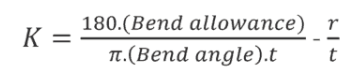 Therefore it is important to have the value correct in 3D CAD software. The value of the K-factor can be calculated taking the average of 3 samples from bent parts and fill in the measurements of bend allowance, bend angle, material thickness and inner radius into the presented formula
Tabs and Notches: Sheet metal parts often require notches to accommodate a screw or other fastener. Notching is a shearing operation in which a section is removed the outside edge of metal strip or part. Notching is typically manual and low-cost process performed with a small range of standard punches.
- Notches length should not extend no more than five times the slot width into the workpiece.
- Notches width should not be narrower than 1.5 x sheet thickness.
- Corner radius for notches should be .5 x sheet thickness.
- The minimum distance from notch to bend should be 3 times the material thickness plus inside bend radius.
- The minimum distance between two notches should be two times the material thickness.
- The tabs on either side of a notched feature should be at least .125 inch or two times the material thickness across and a maximum of five times the part thickness in length.
- The minimum distance between two notches should be two times the material thickness.
- The minimum distance between notch and hole should be 1.2 times the material thickness.
A protrusion from an edge of the sheet metal part is called a tab. It is recommended that tab width should be greater than two times the sheet thickness. Tab length should be less than or equal to five times the tab width, and the minimum distance between tabs should be 1.5 times the sheet metal thickness.
NỘI DUNG TÀI TRỢ

Quảng Cáo Dịch Vụ

Quảng Cáo Sự Kiện

Quảng Cáo Khuyến Mãi

Biểu Trưng & Nhãn hiệu
Hỗ trợ chúng tôi và phát triển doanh nghiệp của bạn với chúng tôi. Mục tiêu của tôi là cung cấp thông tin kỹ thuật với khả năng truy cập sẵn sàng vào các tài nguyên, công thức và tài liệu tham khảo thường cần thiết trong khi thực hiện công việc của mình với tư cách là Kỹ sư hỗ trợ kỹ thuật. Các doanh nghiệp được liệt kê trong Nội dung được Tài trợ đã được lựa chọn cẩn thận vì tính độc đáo của chúng. Tuy nhiên, các quảng cáo liệt kê không được tài trợ sẽ được luân chuyển thay đổi hàng tháng.
ViBa Direct thiếu một ban cố vấn để thực hiện nghiên cứu và thuê các nhà văn với kiến thức kỹ thuật hiện đại. Việc tạo ra một ban cố vấn hiệu quả đòi hỏi nhiều hơn là một lời mời. Nếu không có sự tài trợ của bạn, điều này khó có thể thực hiện. Nếu công ty của bạn có nhu cầu quảng cáo, đặt biểu trưng, thương hiệu, biểu ngữ mời tham gia thảnh viên, hội viên cũng như các bích chương quảng cáo ở đây hoặc trên bất kỳ trang nào khác, xin vui lòng liên hệ với nhóm Dịch Vụ Khách Hàng để biết thêm chi tiết.
Hems: Hemming and seaming are metalworking processes that involve bending and folding sheet metal over and onto itself. The difference between them is that hemming involves folding sheet metal so that the two layers are flush with each, whereas seaming involves folding sheet metal while using a seam to join the two layers. Hems are used to strengthen part edges, hide burrs, and improve appearance. An open hem is one that forms a U or C-shape and might be used to accept a pin for a hinge. Closed hems are basically flat, with the material folded over completely on itself. The inside diameter of an open hem should be equal to or greater than the material thickness, and the “return length” in either case should be at least four times that.
Holes and Slots: Small hole size in sheet metal requires smaller size punching tool which may leads to break during the operation. It is recommended that the diameter of the hole should be equal or more than the thickness of the sheet metal. These should be placed at least 1/16 of an inch from the nearest wall or part edge for materials 0.036-in. thick or less, and 1/8-in. or more from the edge on everything else. Hole and width tolerances will be +/- 0.005 in. unless otherwise specified. Check with the manufacturer if an insert will be used, as additional clearance may be required. If using the eRAPID SOLIDWORKS plugin, all holes and slots should be a minimum of four times the material thickness from any part edge or feature.
Certain distance should be maintained between two extruded holes in sheet metal designs. 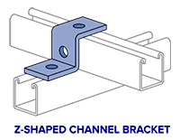 If extruded holes are too close it can lead to metal deformation. It is recommended that the minimum distance between two extruded holes should be six times the thickness of sheet metal.
Offsets: Offsets are Z-shaped bends that might be used on brackets and a Z-Shaped Bracket is a good example. The same rules apply here as with any other bent part—try to keep all the bend radii the same, with 0.030 in. the preferred radius. Also, the parallel planes should be at least two times the material thickness apart, and you can expect Protolabs to maintain a tolerance of +/- 0.012 in. between the two features.
Sheet Metal Tool Bar: To activate the toolbar on the ribbon simply RMB click on any ribbon tab and check the Sheet Metal box.
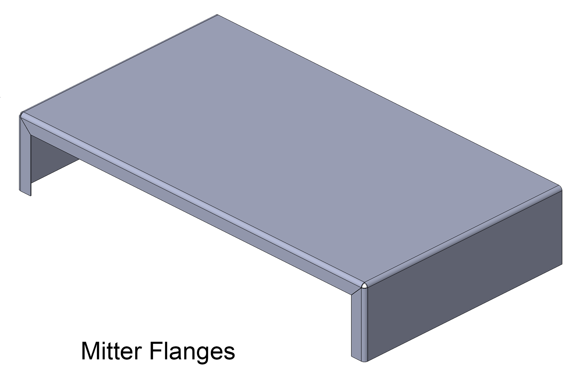
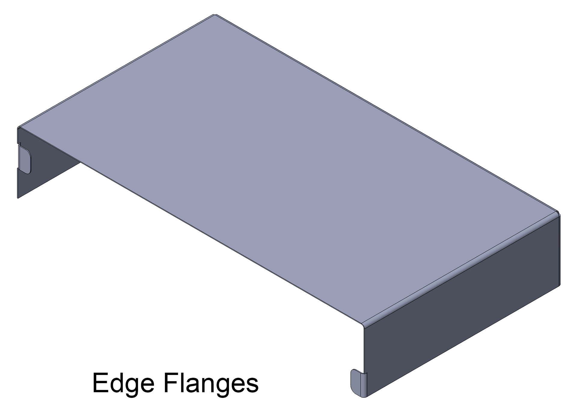
There are specific sheet metal features we can use to create sheet metal body quickly. However, in some circumstances when the design requires certain types of geometry, you can use non-sheet metal feature tools, then insert bends or convert the part to sheet metal. It is important when designing with sheet metal to think about the best approach to design the part. Although it may appear that using non-sheet metal features (such as extrudes and shells) and then inserting bends or converting to sheet metal is quicker, these options are also the least (ít ra, ít nhất) flexible (linh động, linh hoạt). When designing sheet metal parts, the order of design preference is –» Base Flange –» Edge Flange –» Mitter Flange –» Insert Bend Featutes –» Convert to Sheet Metal. When using the Insert Bends and Convert to Sheet Metal features, it is best to apply them as early as possible during part design, preferably right after you create the first non-sheet metal feature.
Sheet Metal Feature:
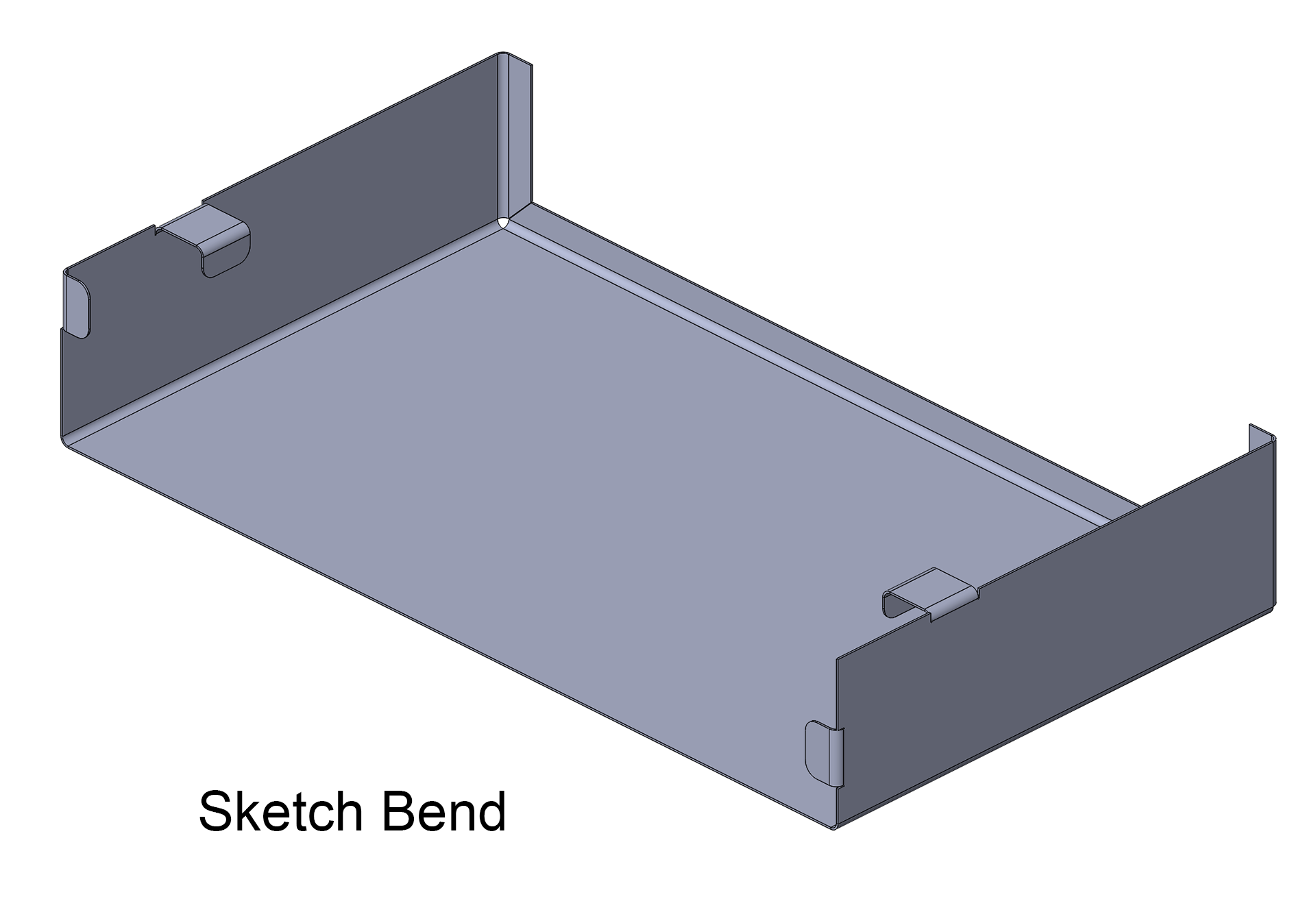
- Base Flange to create sheet metal part –» Mitter to add a series of flanges to an edge/edges –» Hem to curl the edge of a sheet metal piece –» Sketched Bend to add a bend to a selected sketch –» Tab to create tabs (the sketch must be on a plane or planar face that is perpendicular to the direction of thickness of the sheet metal part) –» Closed Corner to extend the face of a sheet metal part.
Sheet Metal Part: When create a sheet metal part, use the Base Flange tool with an open or closed profile sketch.
- Single open contours can be used for extrudes, revolves, sections, paths, guides, and sheet metal. Typical open contours are sketched with lines or other sketch entities. Splines are invalid sketch entities for open contours.
- Single closed contours can be used for extrudes, revolves, sections, paths, guides, and sheet metal. Typical closed contours are sketched with circles, squares, closed splines, and other closed geometric shapes.
- Multiple contained closed contours can be used for extrudes, revolves, and sheet metal. If there is more than one contour, one contour must contain the rest. Using the Contour Select, you can select one or more contours to convert into features. Typical multiple contained closed contours are sketched with circles, rectangles, and other closed geometric shapes. Multiple contained closed contours can also be disjointed.
- Typical multiple disjoint closed contours are sketched with circles, rectangles, and other closed geometric shapes.
Create a Base Flange Feature: Sketch an open or close contour —» Insert —» Sheet Metal —» Base Flange —» Direction (select extrusion direction) —» Depth —» Sheet Metal Parameters —» Thickness (specify requirements and reverse direction if needed.) —» Bend Radius (.04 is minimum) —» Bend Allowance (if K-Factor, Bend Allowance, or Bend Deduction is selected, enter a value. If Bend Table or Bend Calculation is selected, select a table from the list, or click Browse to browse to a table) —» Auto Relief (if Rectangular or Obround is selcted, select Use reief ratio or clear Use reief ratio and set a value for Relief Width and Relief Depth). —» OK.
- K-Factor: If the model is being used for manufacturing, set K-Factor less than 13/.5" for Large Radius bend, 11/.42" for Rotary and Vee bend, 10/.38" for 90° bend or it will not unfold correctly for most bending scenarios.
- Bend Allowance: It's how much material is needed between two panels to accomodate a given bend. Solidworks automatically create this in flat drawing from model. If K-Factor, Bend Allowance, or Bend Deduction is selected, enter a value. If Bend Table or Bend Calculation is selected, select a table from the list, or browse to a table.
- Auto Relief: Select a relief type. If Rectangular or Obround is selected, select Auto Relief and set the value or clear Auto Relief and set Relief With and Relief Depth values.
Convert a solid part to a sheet metal: Non-sheet metal features like Base Extrude, Shell, Rip, and Insert Bends can be build into a part and then insert sheet metal bends. Example: Conical bends are not supported by sheet metal features such as Base Flange and Edge Flange. Therefore, build the part using extrusions, revolves, and so on, then add bends to the conical part. First...
- Design a solid part with all hole feature —» Insert —» Sheet Metal —» Convert to Sheet Metal —»
- If select Sheet Metal Gauges —» select Use gauge table —» select a Table —»
- Sheet Metal Parameters —» select a face as the fix face (the inside of the box) —» Sheet thickness (specify thickness if not using gauge table) —» Default radius for bend (specify radius) —» OK.
SOLIDWORKS SHEET METAL FEATURES
Closed Corner: Use to closed/extend corner between sheet metal flanges.
- Close multiple corners simultaneously.
- Close non-perpendicular corners.
- Apply a closed corner to flanges with bends other than 90°.
- Adjust the Gap distance. The distance between the two sections of material that are added by the closed corner feature.
- Adjust the Overlap/underlap ratio. The ratio between the material that overlaps and the material that underlaps. A value of 1 indicates that the overlap and the underlap are equal.
- Close or open the bend region.
Corner Weld Beads: Open sketch —» Smart Dimension —» click one line —» Ctrl and click the second line —» move the pointer to show the angular dimension preview —» place the angular dimension —» OK
Break a Corner: Sheet Metal —» Corners —» Break Corners/Corner-Trims —» Break Corner Options —» select Corner Edges and/or Flange Faces —» select a Break type: Chamfer or Fillet —» select a value for Distance (chamfer) or Radius (fillet) —» OK.
SPONSORED CONTENT
Your Service Flyer
Your Event Invitation
Your Promotion Ads
Your Logo & Brand
Unfold/Fold: Useful when adding a cut across a bend. First, add an Unfold feature to flatten the bend. Next, add your cut. Lastly, add a Fold feature to return the bend to its folded state. Unfold and fold only the bends that needed for the task.
Hem Feature: Select Hem —» select edge to hem —» choose hem outside or inside —» select hem type (closed, open) —» Shown (teardrop or rolled) —» input value/distance to hem —» OK.
Jog Bend: Jog tool adds material to a sheet metal part by creating two bends from a sketched line. The sketch must contain only one line and the bend line does not have to be the exact length of the faces you are bending. To create a jog feature on a sheet metal part —»
- Select Sheet Metal —» Jog —» Fixed Face (select a face) —» Selections (to edit the bend radius) —»
- Clear Use default radius —» select Use gauge table —» Fixed Face (select a face) —» Selections (to edit the bend radius) —» enter a value for Bend Radius —»
- Jog Offset —» End Condition (select an item) —» Offset Distance (set a value) —» select Reverse offset (to reverse offset direction. Reverse offset only when End Condition is set to Offset From Surface) —»
- Dimension position —» select Outside Offset —» or Inside Offset —» or Overall Dimension —»
- Fix projected length —» select to keep the face of the jog the same length —»
- Jog Position —» select Bend Centerline —» or Material Inside —» or Material Outside —» or Bend Outside —»
- Jog Angle —» set a value —» or Override value (if sheet metal gauge table is used) —» Custome Bens Allowance (to set a custome bend allowance type and value) —» Done.
USING FORMING TOOLS WITH SHEET METAL
Solidworks Forming Tools: Forming tools are a powerful sheet metal feature in SOLIDWORKS. Standard shapes can be dragged onto any sheet metal part to push, pull, and/or cut material with a standard die shape.
1. Model A Formed Part For Most Parts. Always model a completely formed part and unfold to get the flat blank. Don’t make a flat and then try to bend it. This is absolutely impractical in 99% of all applications.
2. Define Sheet Metal Early In The Modeling Process. Always define “sheet metal” immediately so that the “extrude to thickness” function is available. By doing this you will be able to “rollback” to the flat state periodically to confirm that you are making features that can be unfolded. Add all your new features in the “no bends” state (rolled back). Don’t wait until the end to “insert bends” only to find out that your geometry is “unsuitable for unfolding”. When inserting the sheet metal definition on a model with only a single panel, you will get the “No Bends Found” message. This is normal, as all your subsequent features will be placed directly after the sheet metal definition with the model rolled-back. Image: 1001-base
3. Add edge flanges by using Sheet Metal —» Edge Flange. Image: 1002-edge-flange
4. Unfold to add detail features —» Sheet Metal —» Unfold —» select a fixed face —» Bend to unfold —» select all three bends radius —» OK to unfold. Image: 1003-unfold
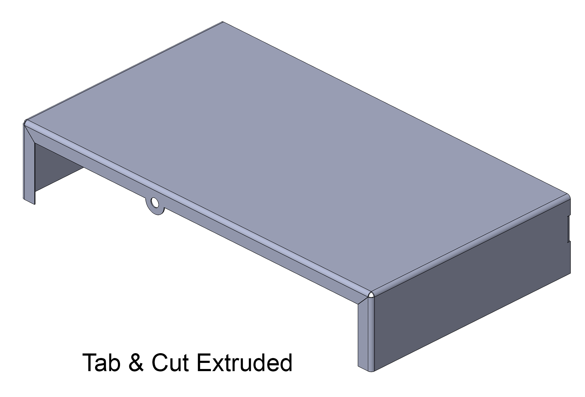
5. Adding Extruded Cut and Thru Holes. Image: 1004-extruded-cut.
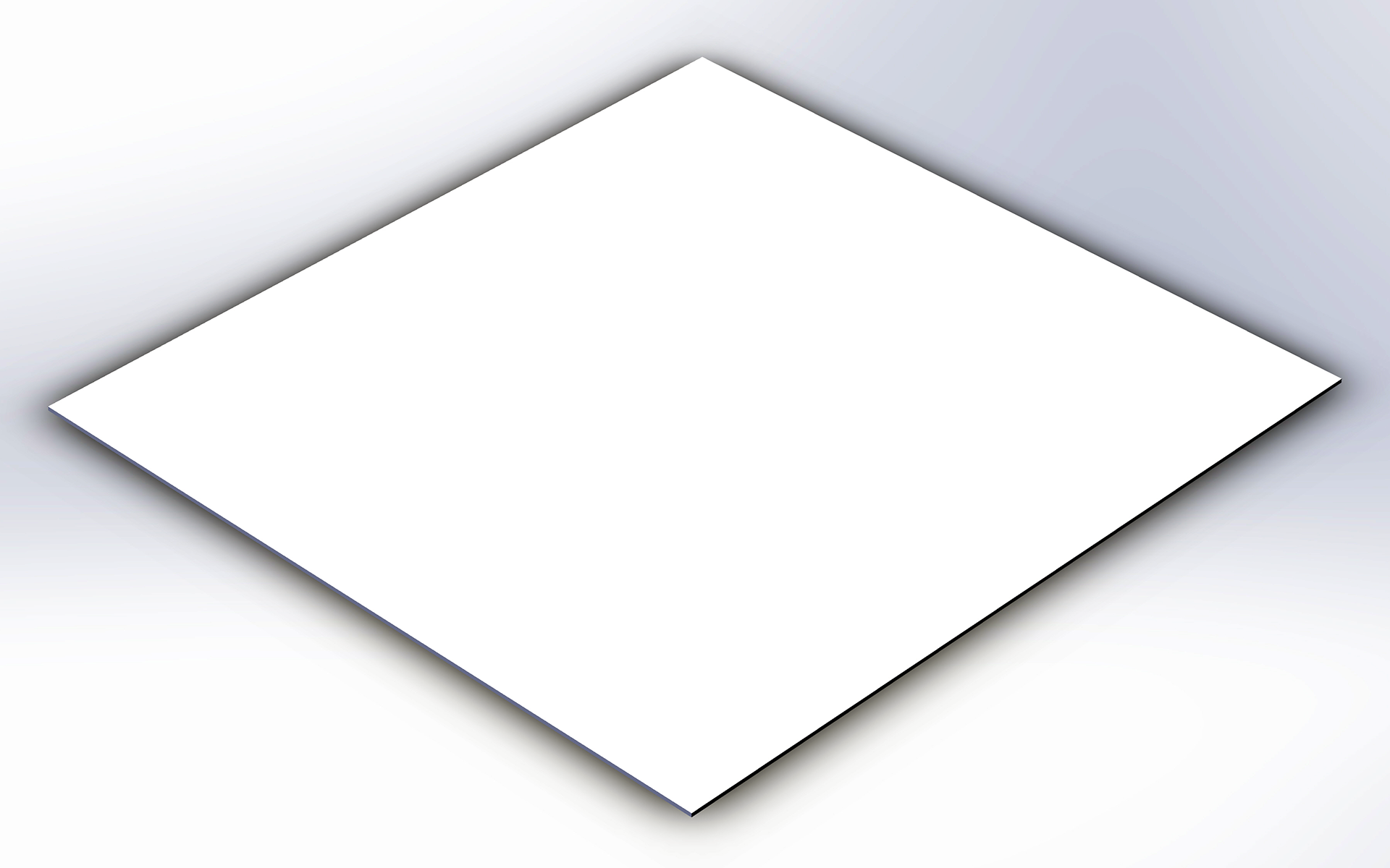
Image: 1001-base
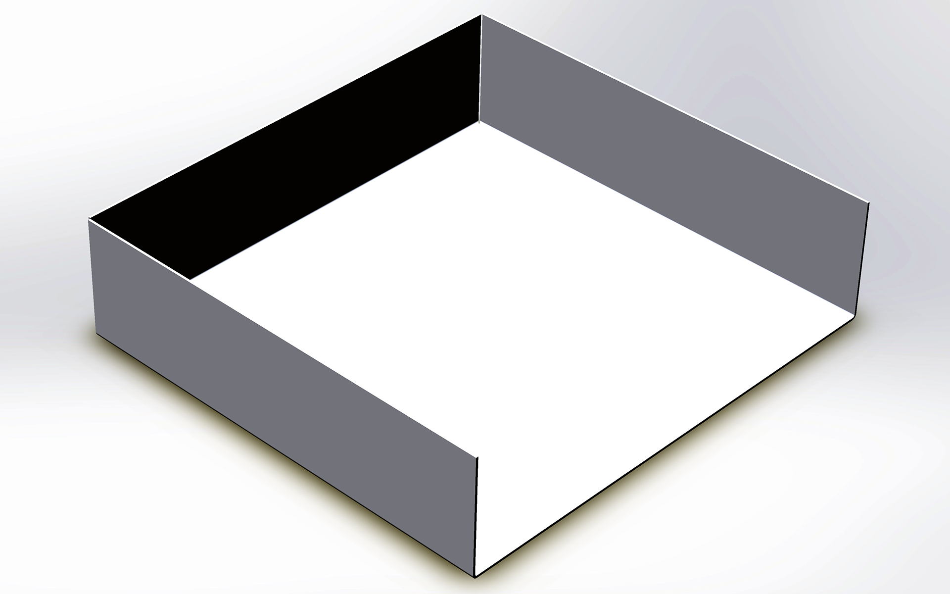
Image: 1002-edge-flange
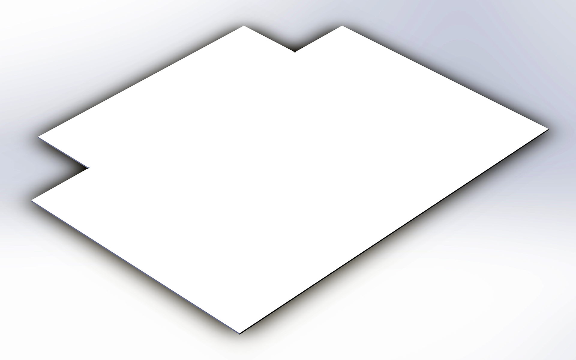
Image: 1003-unfold
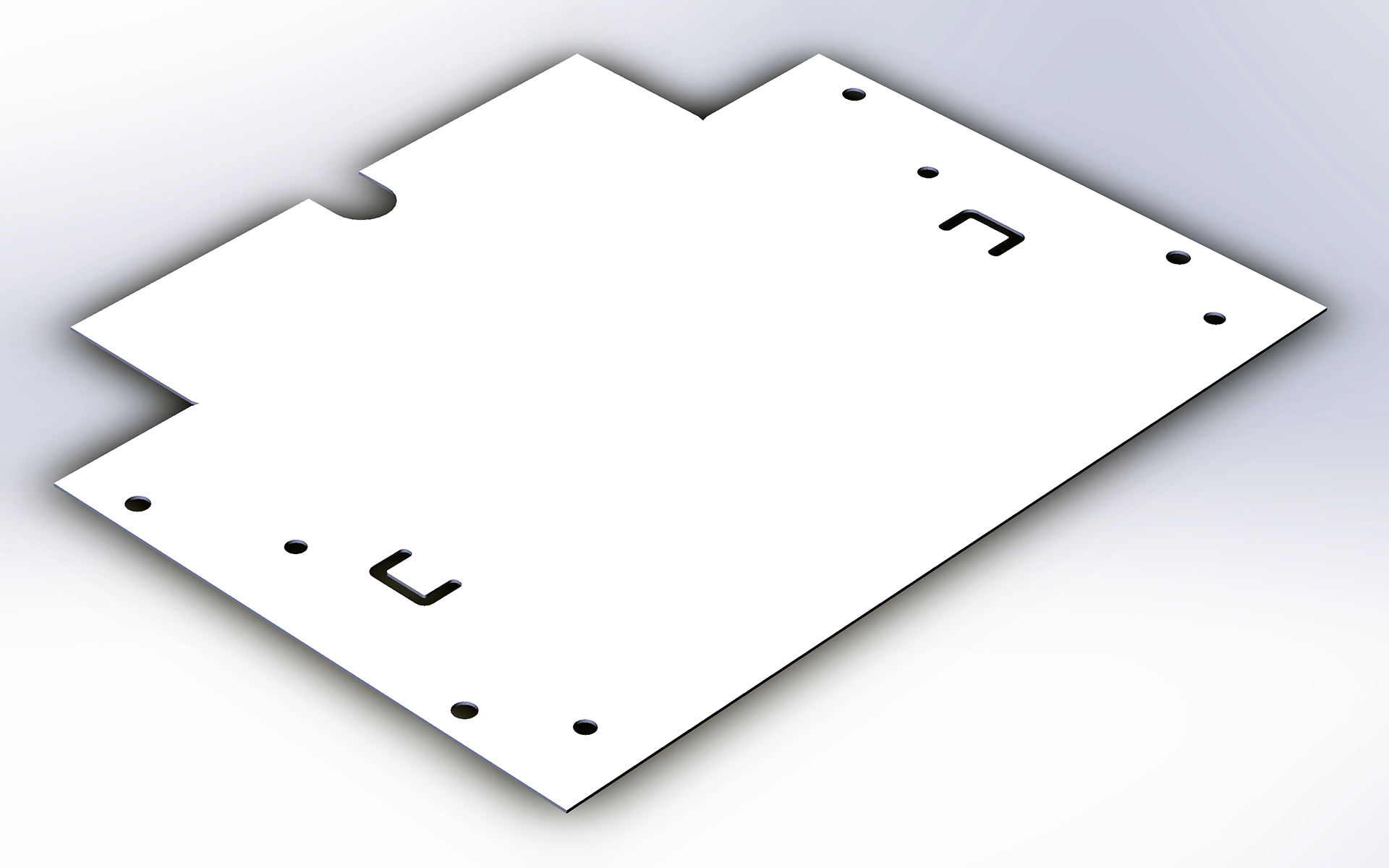
Image: 1004-extruded-cut
6. Folding it back —» Sheet Metal —» Fixed faces is pre-selected —» Bend to fold —» select all previous unbend radius —» OK to fold back. Image: 1005-fold-back
7. Folding and adding bending tabs is one of the easiest and most economical way of making moderately strong joints in sheet-metal parts that will permanently or semi-permanently attach to one another. It requires no screws, rivets, or other pieces of fastening hardware. The metal tabs that are to be bent should be between .06” and .75”. thick. Tabs can vary in size and shape for appearance and to make assembly easier. Design slot shape in triangular, round, or simple notches. These shapes are stronger and last longer than narrow rectangle. The metal should have the ductility to stay in place and not spring back after being bent. The metals most commonly joined using tabs are soft steel, aluminum, copper, and brass.
8. Design an arc lance to add to the bended tabs —» Design Library —» forming tools —» lances —» chose a profile —» RMC —» Open —» Edit the part file to the design intent —» File —» Save as —» to Solidworks forming tools library with a new part name. Image: 1006-arc-lance.
9. Adding sheet metal forming feature —» open a part file —» select the tab surface —» Design Library —» forming tools —» select lthe created lances (forming tools folder) —» dag and drop the forming tool on any surfaces to form —» Rotate Angle (rotate the tool) —» Flip Tool (to flip) —» Ctrl + 8 (Normal view) to define the tool location —» Position —» define the lance location —» OK to form. Image: 1007-lance-feature.
10. The final sheet metal product. Image: 1008-finish-product.
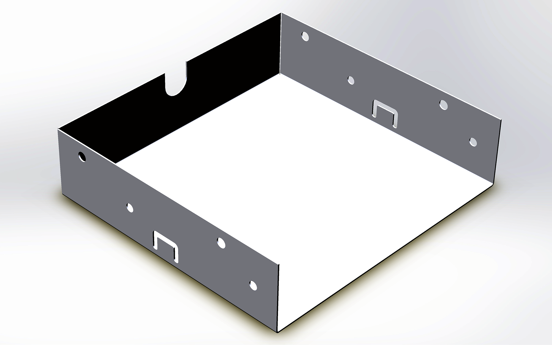
Image: 1005-fold-back
Image: 1006-arc-lance
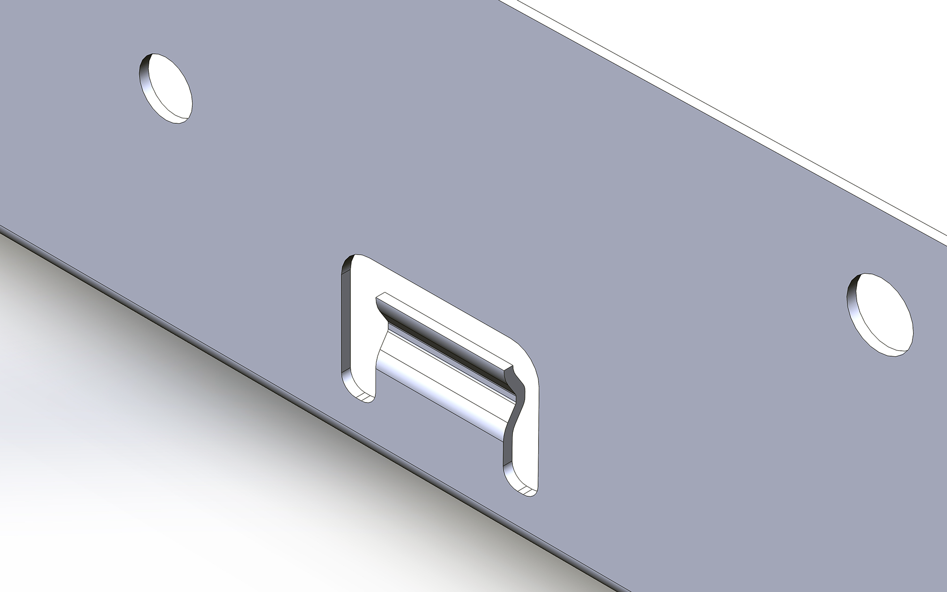
Image: 1007-lance-feature
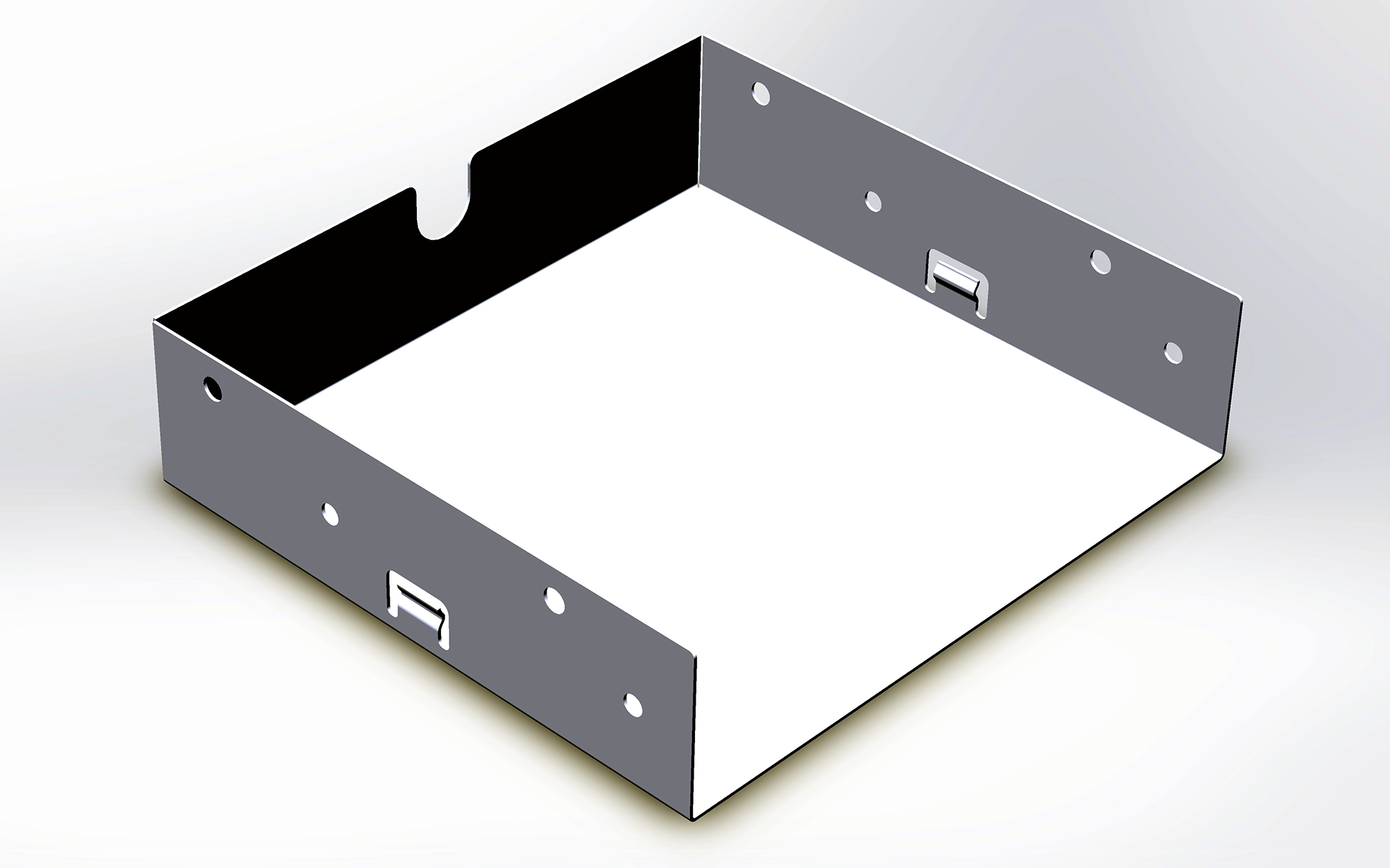
Image: 1007-finish-product
Using Forming Tools with Sheet Metal: If you drag a forming tool (ex: louver) from Design Library onto a sheet metal part surface and it landed sideway/wacky. Here is the solution —» goto Design Library —» select forming tools folder —» RMC —» selected/checked Forming Tool Folder —» select Yes to mark this folder as a forming tools folder.
Note: Before you apply forming tools to sheet metal part, in the Design Library you must designate it folder/contents as forming tools otherwise it will be treated as part file (*.sldprt), not Form Tool file (*.sldftp).
— Add punch IDs to forming tools for easier identification in punch table. In Design Library —» select a forming tool —» RMC —» Open —» File —» Property —» Property Name —» select PunchID —» Type select Text —» for Value/Text Expression, type a punch ID —» OK —» Save the part.
SOLIDWORKS MULTIBODY SHEET METAL PARTS
Multibody Sheet Metal Parts: To create complex sheet metal designs. Multibody sheet metal parts can consist of multiple sheet metal bodies or a combination of sheet metal and other bodies such as weldment bodies. Each body has its own sheet metal and material definition, flat pattern, and custom properties. These body-related properties can be used in BOMs and drawings. Each body can be isolated and displayed individually in drawings. .....developing subjects.


